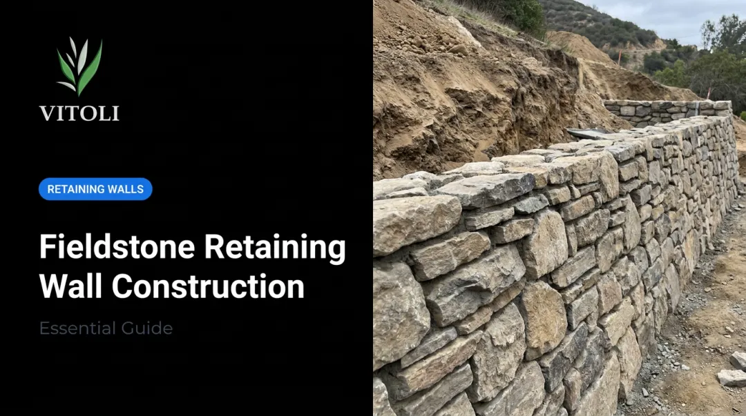
Introduction
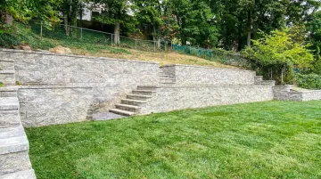
A segmental retaining wall looks simple on the surface: stacked concrete blocks holding back a slope. Low walls under 3 ft can be a capable DIY project. But once you're working on hillside terrain, managing significant grade changes, or building past 4 ft, the margin for error shrinks fast.
The consequences of getting it wrong aren't cosmetic. An unlevel base course compounds into a leaning wall. Missing drainage lets hydrostatic pressure build until blocks crack or blow out. Omitting geogrid on a taller wall doesn't cause gradual settling — it causes outright rotation and collapse.
On hillside properties in Los Angeles County and Ventura County, these aren't hypothetical risks. Seismic loads, expansive clay soils, and strict local codes all factor into the design from day one.
This guide covers what segmental retaining walls are, how to design and install them correctly, and where professional engineering becomes non-negotiable.
Key Takeaways
- Segmental retaining walls use interlocking dry-stacked concrete units — no mortar or poured footing needed
- A perfectly level, well-compacted base course is the single most important factor in wall longevity
- Walls over 4 ft require engineered design and local permits in California
- Drainage is mandatory: 12 in. of gravel fill plus a perforated drain pipe at every wall
- Geogrid reinforcement is required for most walls over 3 ft — placement and spacing must match the engineered plan
What Are Segmental Retaining Walls?
Segmental retaining walls (SRWs) are gravity structures built from dry-stacked concrete masonry units — no mortar, no poured footing. According to the Concrete Masonry and Hardscapes Association (CMHA), SRWs resist destabilizing forces from retained soil and surcharge loads through their combined self-weight, the frictional interlock between units, and a controlled backward lean called wall batter.
Two Core Types
Conventional gravity walls rely solely on block mass and setback. Practical for lower applications — typically up to 3–4 ft on level ground with favorable soil — they require no special reinforcement.
Soil-reinforced (MSE) walls embed horizontal geogrid layers that anchor into a reinforced soil mass behind the wall. This substantially increases the load the system can handle, allowing walls to reach heights that block mass alone cannot support.
Why SRWs Work Well on Hillside Sites
Both wall types share characteristics that make them particularly well-suited to steep, constrained, or irregularly shaped sites:
- Blocks are hand-carriable, so tight access and no-crane conditions aren't a problem
- Curves, corners, and step-downs all work with standard block systems
- Multiple colors, textures, and face profiles are available to match site aesthetics
- Installation costs are typically lower than poured concrete for comparable wall heights
- Walls can be loaded as construction progresses — no cure time required
Design Considerations Before You Build
Wall Height and Engineering Thresholds
Height determines complexity. CMHA guidelines recommend engineered design by a registered professional for any SRW with a total design height exceeding 4 ft (1.21 m). VERSA-LOK's installation documentation mirrors this — walls over 4 ft supporting significant loads require a licensed civil engineer.
In California, the permit threshold aligns with this benchmark. Both the 2022 and 2025 California Building Code, Section 105.2 exempt retaining walls not exceeding 4 ft measured from bottom of footing to top of wall, unless the wall supports a surcharge or impounds liquids. LA County and Ventura County B-49 repeat the same threshold with additional submittal requirements.
Site Geometry and Slope Conditions
The slope above and below the wall changes the structural math significantly:
- A steep backslope increases lateral earth pressure, which lengthens required geogrid layers and deepens excavation
- Proximity to structures adds surcharge load (even a parked vehicle behind the wall changes the design)
- CMHA minimum embedment depths reflect toe slope conditions: H/20 for level toes, H/10 for 3:1 slopes, H/7 for 2:1 slopes, with an absolute minimum of 6 in.
Drainage Planning
Drainage isn't optional. CMHA specifies three required drainage components working together:
- Gravel fill: Minimum 12 in. (305 mm) of free-draining material behind the wall face
- Perforated drain pipe: 3 or 4 in. diameter at the base, venting every 50 ft maximum
- Geotextile filter fabric: Separates gravel fill from retained soil to prevent fines from migrating into and blocking the drainage zone
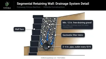
Allan Block also notes that horizontal filter fabric above the gravel column stops soil from washing down from above — treating drainage as a layered system, not a single pipe.
Southern California Site Conditions
For properties in Los Angeles County and Ventura County, standard SRW design tables aren't enough. Seismic loading (CMHA uses pseudo-static Mononobe-Okabe analysis), expansive clay soils, and variable slope conditions create site-specific demands that generic design tables can't address.
LA County Building Code Manual 1807.2 requires retaining walls to be designed for stability against overturning, sliding, excessive foundation pressure, and water uplift — addressed simultaneously, not sequentially. Vitoli Builders' site assessment process evaluates soil composition, slope grade, drainage patterns, and load requirements before any design work begins, which is exactly the data these calculations require.
How to Install a Segmental Retaining Wall
Every phase of SRW installation depends on the one before it. An error in excavation carries through the leveling pad, into the base course, and amplifies with every course above. Get the foundation right, and the rest follows.
Prerequisites and Site Preparation
Before breaking ground:
- Verify finish grades match design drawings and mark all utility locations
- Identify drainage patterns that need redirection around wall ends
- Confirm material staging and equipment access are workable for the full build
Two tasks set the stage for everything that follows:
Excavation — Size the trench to accommodate full block depth, plus a minimum of 6 in. to the front and 12 in. to the back. On sloped ground, step the leveling pad down with the grade rather than following the surface, so embedment depth stays consistent along the entire wall length.
Leveling pad — Compact a minimum 6 in. layer of crusher run (21A, ABC stone, or ¾-minus) using a jumping jack or vibratory plate compactor. VERSA-LOK specifies compaction to 95% of maximum standard Proctor density. Place geotextile fabric along the bottom and back of the excavation before adding stone, per manufacturer guidance.
Step-by-Step Installation
1. First course Set each block level front-to-back and side-to-side, then run a string line across the full course to verify alignment. Align blocks by their backs or slots, not the textured face. Any level error here multiplies with every course above.
2. Drainage installation After the first course is set, place the perforated drain pipe directly behind the wall base. Backfill over and around it with clean ¾ in. gravel (#57 stone). Fill any open block cores with gravel at this stage.
3. Subsequent courses
- Clean debris from block tops before each course
- Install manufacturer-specified shear pins or connectors (VERSA-LOK requires two pins per unit, recessed about 1 in. below the top surface)
- Stagger vertical joints in running bond pattern
- Backfill with clean gravel in lifts no greater than 8 in., compacting each lift
- Keep heavy compaction equipment at least 3 ft from the wall face
4. Geogrid installation (when required) At manufacturer-specified course heights, lay geogrid horizontally on the block surface and extend it back into the soil to the required length. CMHA specifies L ≥ 0.6H, with an absolute minimum of 4 ft (1.2 m). Secure with the next block course, then backfill and compact before continuing. Geogrid placement intervals and lengths must match the engineered design exactly — no field substitutions are acceptable.
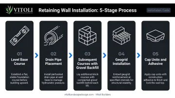
5. Cap units Secure caps with manufacturer-recommended flexible construction adhesive. VERSA-LOK uses two continuous ¼ in. beads of their specified adhesive — rigid adhesives and mortar are not acceptable. Confirm caps are level and flush.
Post-Installation Checks
Before final grading, walk the wall and inspect each of the following:
- Each course is plumb — not leaning forward
- Gravel fill is visible and consistent behind the wall face
- Caps are fully adhered with no movement
- Drainage outlets at wall ends are clear and directed away from the structure
- No soil is pushing through face joints (indicates missing gravel fill or absent geotextile)
Once grading covers the wall base, these problems become invisible — until they reappear as structural failures.
Common Installation Problems and Fixes
Unlevel or Shifting Base Course
Problem: The first course shifts laterally or sits out of level after backfilling begins.
Likely cause: Inadequate leveling pad compaction or insufficient embedment depth. The pad shifts under load before the wall has enough height to resist it.
Fix: Excavate and rebuild the leveling pad with properly compacted aggregate. Shimming or adding filler material is not a structural correction.
Hydrostatic Pressure Damage and Bulging
Problem: The wall face bulges or cracks, or water seeps through the face rather than exiting cleanly at drain outlets.
Likely cause: Missing or blocked drain pipe, insufficient gravel fill depth, or retained soil washing into the drainage zone because geotextile fabric was omitted.
Fix: If still under construction, correct gravel fill depth and install filter fabric before continuing. On a completed wall, a licensed professional needs to assess whether partial disassembly is the only path to a real fix — surface patches won't address the pressure behind the wall.
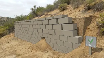
Geogrid Omission or Improper Placement
Problem: The wall leans forward or shows upper-course rotation on walls taller than 3–4 ft.
Likely cause: Geogrid was skipped, placed at insufficient intervals, or not extended to the required depth. An ASCE case study of a geosynthetic-reinforced SRW failure documented complete collapse three months after construction — during monsoon season — attributed to reinforcement deficiencies.
Fix: There is no field patch for this. The affected section must be rebuilt with geogrid installed per the engineered design. Skip the reinforcement schedule once, and the wall essentially becomes a countdown.
All three of these failure modes share the same root: steps that were rushed or skipped during the prep and build phase. Getting the base, drainage, and reinforcement right the first time is far cheaper than rebuilding any section of wall after the fact.
Pro Tips for a Long-Lasting Segmental Retaining Wall
- Use the manufacturer's manual for your specific block system — batter, shear pin placement, geogrid connection details, and maximum gravity heights all vary by product. Deviating from them invalidates the structural assumptions behind the manufacturer's design tables.
- Step the leveling pad down with the terrain on sloped sites. A consistent embedment depth along the full wall length is what prevents undermining at low points.
- Don't treat geogrid intervals as approximate. The engineered design specifies them for a reason. Spacing that's close but wrong is structurally the same as omitting the grid.
- Keep compaction equipment 3 ft back from the wall face during backfilling. Equipment too close pushes the structure before it has enough mass to resist lateral force.
- On any wall over 4 ft, on a hillside, adjacent to a structure, or subject to vehicle or equipment loads — get a licensed hillside construction specialist involved before breaking ground. In Southern California, seismic activity, expansive soils, and local code requirements add complexity that site-specific engineering must address.
For Southern California hillside properties in particular, those variables rarely appear in isolation. Vitoli Builders works specifically in this terrain, combining in-house engineering with hands-on construction experience across Los Angeles County and Ventura County.
Frequently Asked Questions
What are segmental retaining walls?
Segmental retaining walls are gravity structures built from dry-stacked interlocking concrete masonry units. They resist lateral soil pressure through combined unit weight, friction between courses, and controlled wall batter — with no mortar or frost-depth concrete footing required.
How high can a segmental wall be built?
Unreinforced gravity SRWs are generally limited to 3–4 ft depending on soil conditions and the specific block system used. With geogrid reinforcement and proper engineering, walls can reach significantly greater heights. Any wall exceeding 4 ft typically requires a licensed engineer and local building permits.
What is the 1-to-3 rule for retaining walls?
The 1-to-3 rule states that a gravity wall's base width should be at least one-third of its height. For SRWs, CMHA replaces this with engineered ratios — embedment depths of H/20 to H/7 and geogrid lengths of at least 0.6H — based on actual site conditions rather than a simple rule of thumb.
What are the four types of retaining walls?
The four main categories are gravity walls (which includes segmental retaining walls), cantilever walls, sheet pile walls, and anchored or tieback walls. SRWs belong in the gravity category, relying on mass and friction rather than structural connection to resist soil pressure.
Do segmental retaining walls need drainage?
Yes — drainage is a structural requirement, not a preference. CMHA specifies a minimum of 12 in. of free-draining gravel fill behind the wall face, plus a perforated drain pipe at the base. Hydrostatic pressure from inadequate drainage is one of the primary causes of SRW failure.
Do segmental retaining walls require permits in California?
Walls under 4 ft — measured from footing bottom to wall top — are generally exempt under the California Building Code, provided they don't support a surcharge or impound liquids. This threshold applies in LA County and Ventura County. Walls at or above 4 ft require a permit and engineered drawings, so confirm requirements with your local building department before starting.